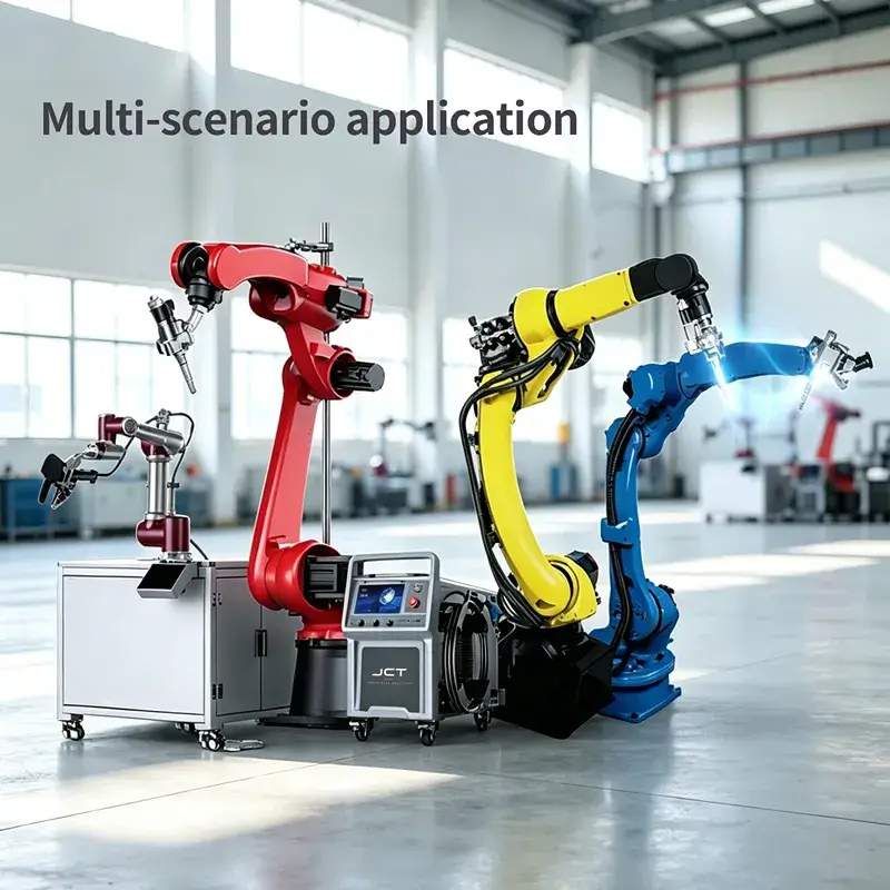
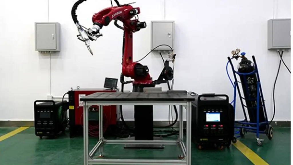
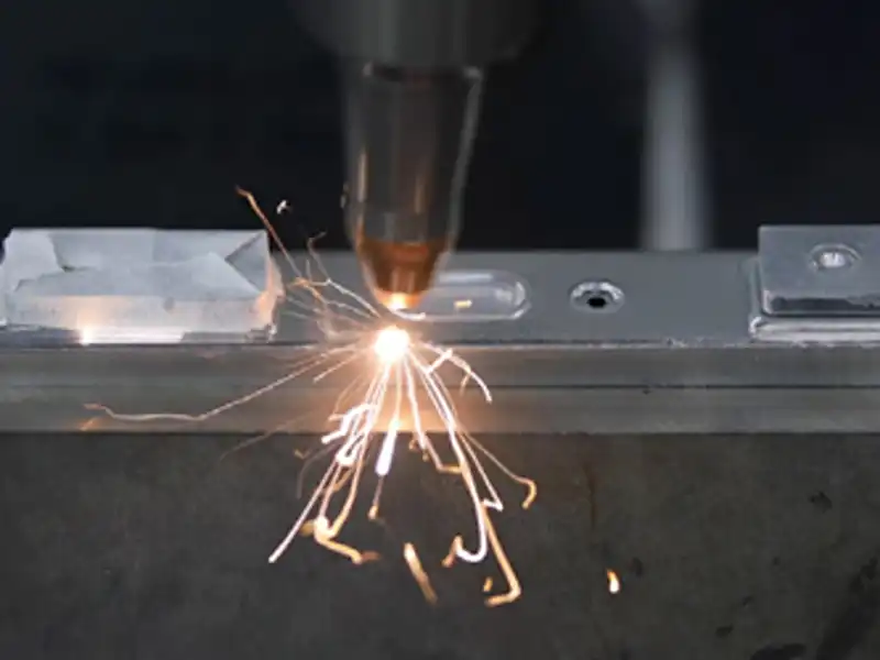
JCT 6-axis industrial robot arm intelligent automatic welding
Paremeter table
| Subsystem Category | Configuration Options | Technical Specifications & Remarks |
|---|---|---|
| Automated Laser Sources | STR-AW350 / STR-AW450 / STR-AW550 / STR-AW550pro / STR-AW850 | Core fiber laser sources with customizable core diameters (14µm to 30µm). |
| Robotic Arm Compatibility | FANUC, Yaskawa, STEP, CRP, and other major brands | Standard industrial and collaborative robot integration with ISO flange compliance. |
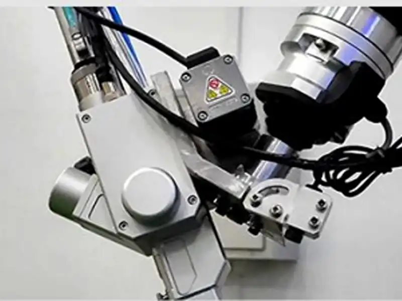
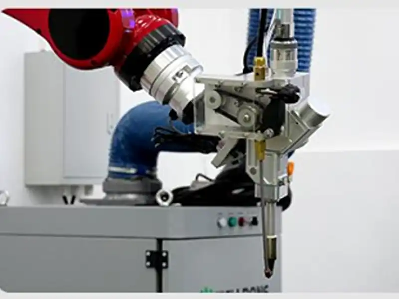
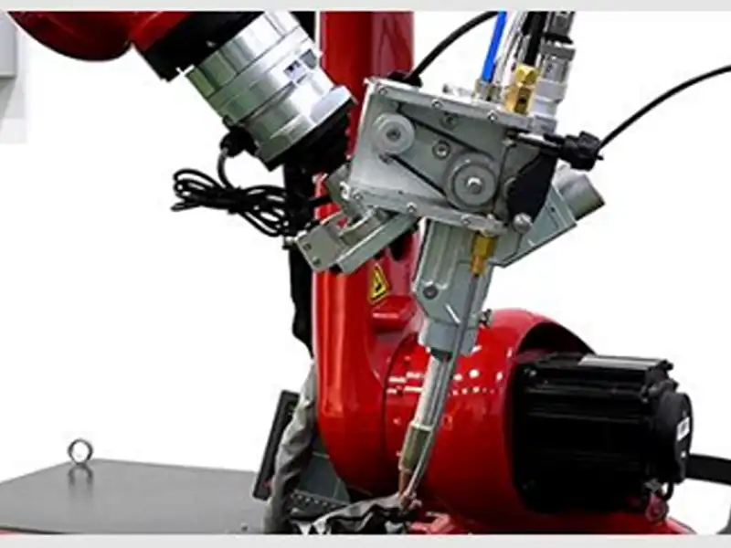
| Welding Heads & Optics | STR-RSD-20A Smart Dual-Pendulum Heads | Lightweight design (<4.5KG), 140° rotating flange, anti-collision safety. |
| Servo Wire Feeders | STR-DW02C, STR-DW04, STR-RWF-10A, STR-RWF-10B | Pull-push wire feeding mechanism to eliminate wire tangling and slippage. |
| Processing Capacity | 0.35mm to 7mm Metal Sheets | High-precision fusion across stainless steel, carbon steel, and aluminum alloys. |
| Control Interface | Integrated Smart Control Cabinet | Multi-parameter adjustment, built-in process libraries (>16 sets), IP54 protection. |

Core Technological Advantages
Engineered for collision safety, flawless wire feeding, and multi-axis flexibility in automated cells
Anti-Collision Safety System
Automatically triggers an immediate emergency stop upon any angular collision, followed by rapid, precise positional resetting to protect the torch head
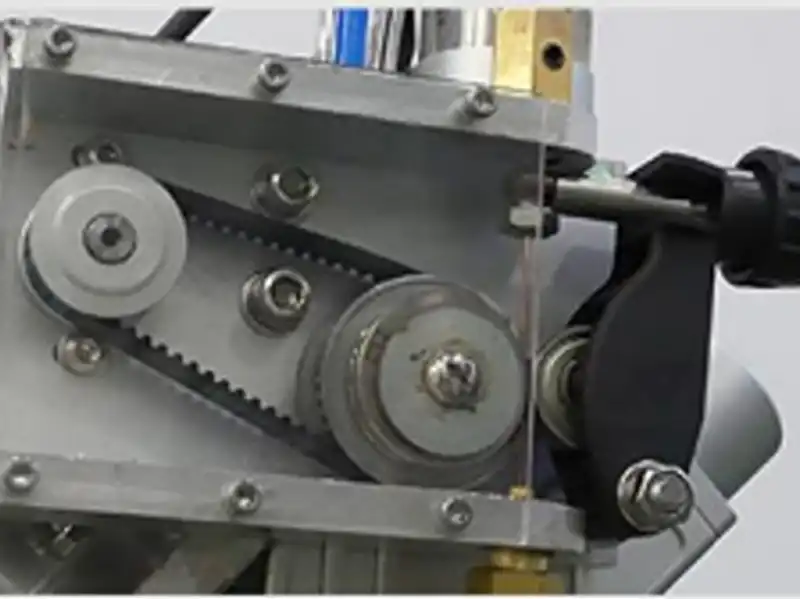
Pull-Push Wire Feeding Mechanism
Shortens the distance between drawing and pushing mechanisms, ensuring ultra-smooth wire delivery and eliminating wire feeding jams.
Ultra-Lightweight Torch
Integrates torch components, drawing assembly, and adapter flanges into a compact structure compatible with robot payloads $\ge$ 8KG.
140° Flange Connection
Enables 360° continuous fiber cable rotation without twisting or binding, supporting multi-angle 3D robotic welding.
Red Line Crosshair Focus
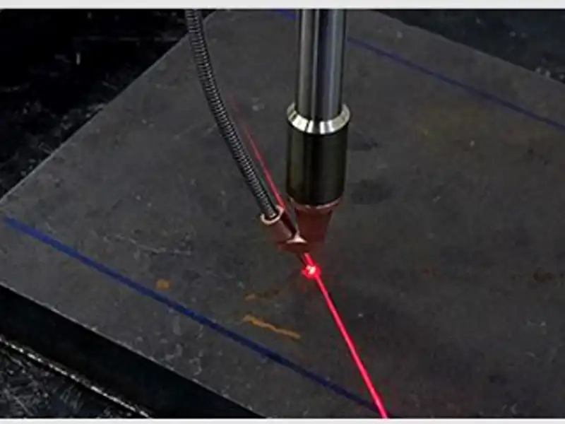
Overlaps the laser beam with a precise red crosshair for instant, effortless focal alignment, slashing setup time.
Hose-Locked Wire Routing
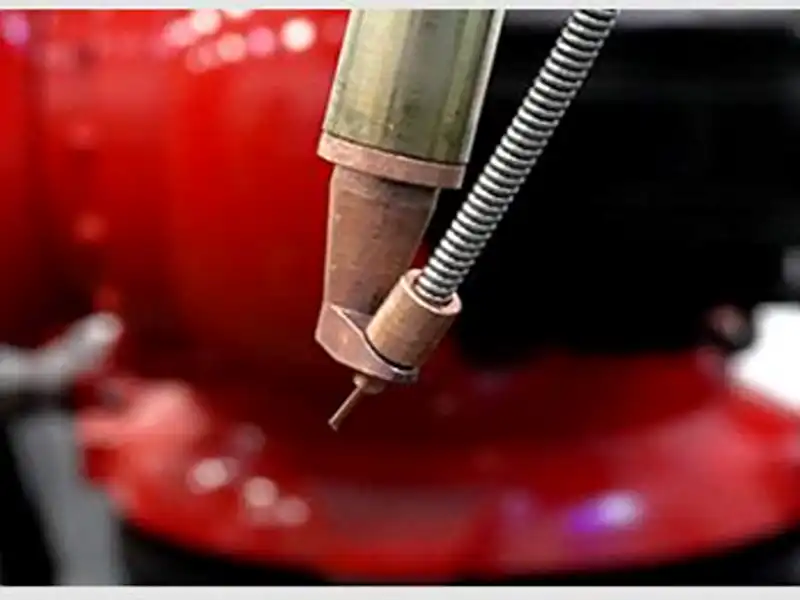
Maintains secure wire guidance even at steep 40-degree welding angles, ensuring the wire never deviates from the laser spot
Automated Processing Workflow
Step-by-step workflow of operating JCT automated laser welding systems, featuring preset process libraries and one-key parameter switching.
Step 1 - Path Programming
Program the robotic trajectory and select pre-stored welding parameters (>16 process sets) via the smart control interface
Step 2 - Focal Calibration
Utilize the red crosshair laser alignment tool to verify focal length instantly
Step 3 - Automated Execution
The robotic arm executes multi-axis movement while the pull-push wire feeder and dual-pendulum head maintain stable fusion on 0.35mm to 7mm metals
Step 4 - Real-Time Monitoring
Dual safety interlocks and status tracking ensure defect-free seam formation across complex industrial workpieces.
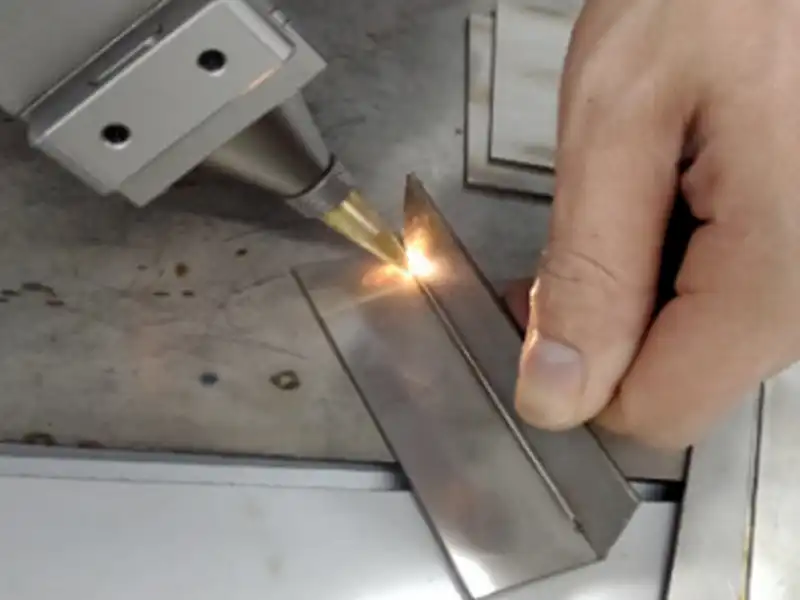
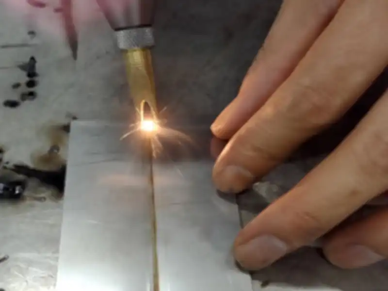
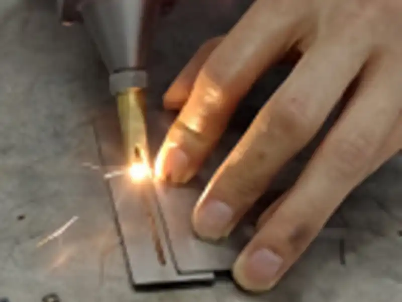
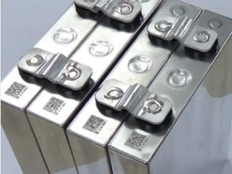
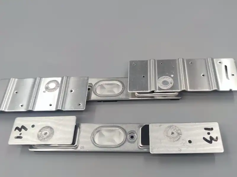
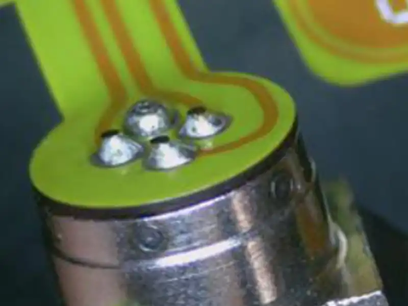
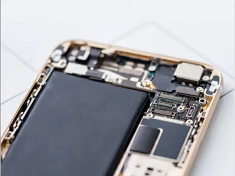
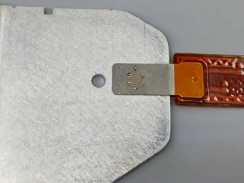
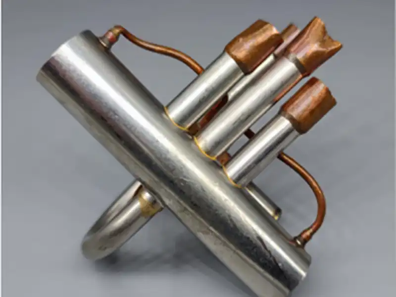
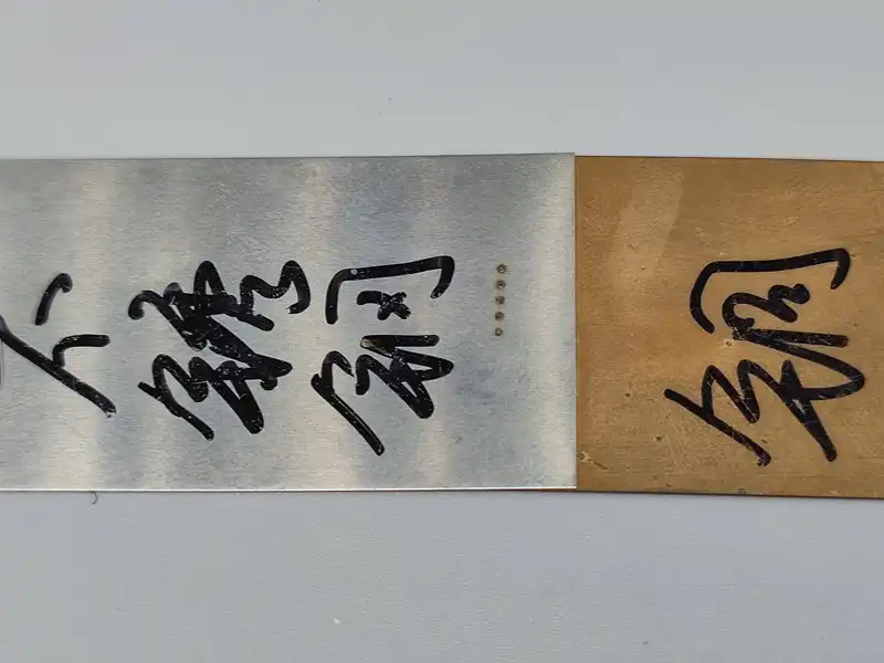
Welding Sample Showcase
Explore high-precision laser welding results on stainless steel, carbon steel, and aluminum by JCT systems
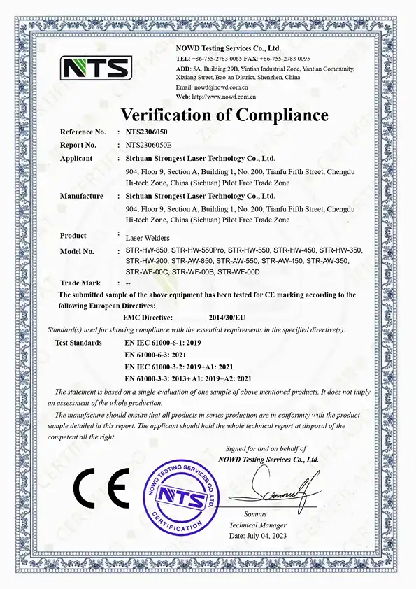
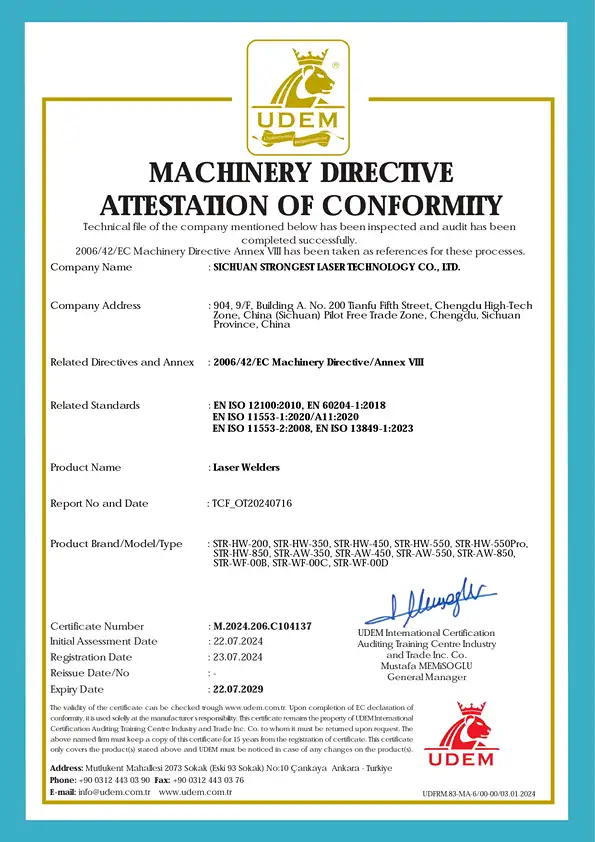
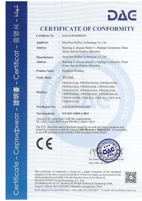
GLOBAL PARTNERSHIPS
Trusted by Industry Leaders Worldwide
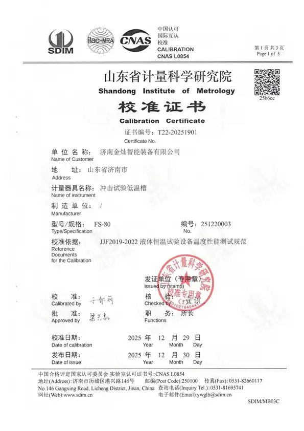
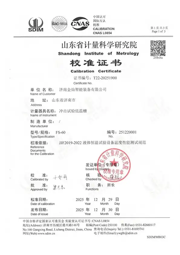
We take pride in powering the success of top-tier global manufacturers, research institutions, and industrial leaders. Our advanced laser and testing solutions are trusted worldwide to deliver uncompromising quality and peak performance.


FAQ
Q1: What is a laser welding robot (automated laser welding system)?
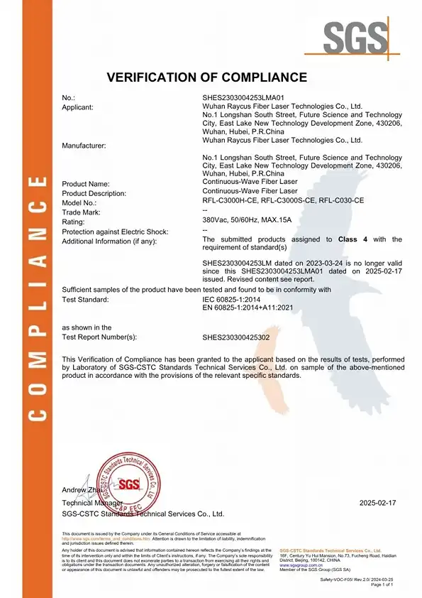
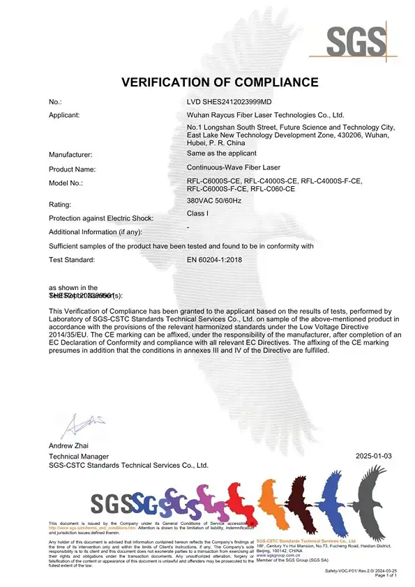
laser welding robot (or automated laser welding integration system) is an advanced industrial manufacturing cell that combines a high-precision multi-axis robotic arm, a high-power fiber laser source, a smart dual-pendulum welding head, and automated wire-feeding mechanisms. Designed for precision metal fabrication ranging from 0.35mm to 7mm, it automates complex 3D trajectory welding with extreme repeatability, minimal thermal distortion, and high industrial production.
Q2: Can this automated system be integrated into an existing robotic cell in our workshop?
Yes. Its modular architecture and rich external I/O control interfaces allow smooth integration with existing robotic arms, safety enclosures, and external fixtures.
Q3: What is the advantage of the pull-push wire feeding mechanism over traditional single feeders?
By shortening the distance between drawing and pushing motors, the pull-push system eliminates wire friction, prevents wire bending or jamming, and ensures exceptionally smooth wire deposition.
Q4: How does the 140° flange connection benefit multi-axis robotic welding?
The specialized 140° flange allows the optical fiber cable to rotate up to 360° freely without twisting, kinking, or blocking light transmission during complex 3D robotic trajectories.
Q5: Are complex programming skills required to set up welding parameters for new workpieces?
A: No. The system includes a smart control cabinet pre-loaded with over 16 sets of expert process libraries, enabling operators to recall and adjust parameters quickly via the touch screen.
Q6: What routine maintenance is required for the automated laser welding head and wire feeder?
Routine maintenance are mainly periodic inspection , cleaning of the protective optical window, checking drive roller tension on the wire feeder, and clearing dust filters.
Q7: What kind of engineering support does JCT provide for automated cells?
We provide comprehensive 24/7 remote video diagnostics, and direct engineering guidance to ensure seamless cell commissioning